Heads Up Display
This is a short note on how to turn your Digirule 2U to an auxiliary little display for up to 2 different parameters.
You can use it to display all sorts of things such as your battery charge level, whether you have new email and any other “event” you can describe with an integer number from 0 to 255.
Here is what we are aiming for:
What is the display?
Every Digirule, from version 2 to 2U is equipped with two rows of LEDs:
The upper row, labeled
A7, A6, A5...A0, which is normally used to display the current memory address in binary; andThe lower row, labeled
D7, D6, D5...D0, to display the byte value at the current memory address, also in binary.
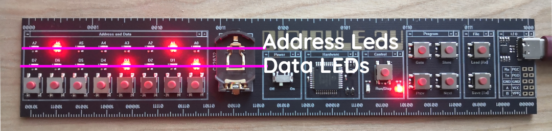
The Digirule 2U with its two LED “bars” formed by the address and data leds.
When the Digirule powers up, the default behaviour is to have the address LEDs to be showing the current memory address.
It is however possible, to also control them by setting the third bit of the status register to 1; and
writing the byte value to depict at address 254.
Driving the data LEDs is much more straightforward, by just writing the BYTE value to address 255.
These two rows of LEDs can be used to display a binary number or they can be used as two “bar” displays, depicting a
bar filling up by depicting the numbers 1, 3, 7, 15, 31, 63, 127, 254.
So, the main idea is to write a program that displays the two numbers to the displays and when data becomes available on the serial port, it reads it in and goes back to displaying them.
But how do we select the display and send those numbers in?
What are its commands?
Our little display is built around a very very simple protocol: /<display><number>.
/ is used as the starting character. This notifies the code to read in the next value which here is either a 0 or
1 and this corresponds to which bar to set.
Send /0 to select the Data LED bar, or /1 to select the
address LED bar. The final step is to read in the BYTE value which is an integer number from 0 to 255.
So, to set the Data LED bar so that it appears 50% lit (just 4 LEDs being lit), we would send /0015 and similarly,
to send the same value to the Address LED bar we would send /1015.
To simplify things, the BYTE value to be depicted to the LEDs must be 3 digits long. Which means that if you wanted to
send 0, you really have to send 000.
This brings about an interesting point about this little demo because to an extend, it is identical to Converting numbers to strings.
This is because, we want to be able to send the number to the display in human readable form and this means that it will
have to be in “ASCII”. That is, instead of sending A (which represents the number 65), we would be sending 065 and
this means that before storing the value 65, we need to calculate
\((\text{byte}_0 - 48) \cdot 100 + (\text{byte}_1 - 48) \cdot 10 + (\text{byte}_2 - 48)\).
The reason we are subtracting 48 here, is because 48 is
the ASCII code that corresponds to the symbol that
we know as zero.
So, the interpretation of 065 simply boils down to evaluating
\((48 - 48) \cdot 100 + (54 - 48) \cdot 10 + (53 - 48)\) prior to storing the
received value (\(65\)) to either the upper or lower display.
Knowing how this is handled now only leaves putting it together with communications…
How to handle the communication?
The logic for this is very simple. For 99% of its running cycle, the progam reads the two values to depict from memory and sends them to the LED displays.
Without communications, this is really straightforward:
 1.EQU status_reg=252
 2.EQU addr_led_bit=2
 3BCLR addr_led_bit status_reg # Enable control of the Address LEDs
 4
 5display_values:
 6COPYRR M1 254
 7COPYRR M2 255
 8JUMP display_values   # For ever display M1 and M2
 9
10M1:
11.DB 32
12M2:
13.DB 16
And, when the time comes to update the values, the program needs to jump out of its display loop, check if the received message fits the protocol, receive the string, do any necessary conversions and go back to displaying the new values.
It probably reads much more complicated than it really is.
The main loop remains the same, but we now add a COMRDY to check if a message is being received:
 1# ...
 2# ...
 3
 4check_input:
 5COMRDY
 6BCRSS zero_bit status_reg # If data is received COMRDY marks the
 7JUMP load_new_values      # Zero flag and, here, branches out to load_new_values
 8display_values:
 9COPYRR M1 255
10COPYRR M2 254
11JUMP check_input
The next part is simply reading in bytes and converting them to a number:
 1# ...
 2# ...
 3
 4load_new_values:
 5BCLR carry_bit status_reg
 6COMIN
 7SUBLA 47                    # Is it the / character?
 8BTSTSS zero_bit status_reg
 9JUMP display_values         # If not go back to displaying the values
10BCLR carry_bit status_reg
11COMIN
12SUBLA 48
13BTSTSC carry_bit status_reg  # Is the display a positive number?
14JUMP display_values
15ADDLA M1
16COPYAR R0
17BCLR carry_bit status_reg
18COMIN                       # Receive the first byte...
19SUBLA 48
20COPYAR R1
21COPYLR 100 R2               # Multiply by 100
22MUL R1 R2
23COMIN                       # Receive the second byte...
24SUBLA 48
25COPYAR R2
26COPYRA R1
27COPYLR 10 R1                # Multiply by 10
28MUL R2 R1
29ADDRA R2                    # Add it to the previous product
30COPYAR R2
31COMIN                       # And finally receive the third byte
32SUBLA 48
33ADDRA R2                    # And add it to the previous sum.
34COPYAI R0                   # Now transfer the result to either M1 or M2
35JUMP display_values         # Get back to the main loop
And that is basically it. The only other thing that this code does is deciding whether to send
the received and converted value to M1 or M2 depending on the bar selection number (the first
value right after /).
Here is the complete code listing from dg_asm_examples/hud/.
 1# Implements a simple two bar Heads Up Display
 2# To use the two LED display bars on the Digirule as HUDs send the following
 3# message to the COM port:
 4# /<display><number>
 5# For example: /0128 sets display 0 to 128 and /1128 sets display 1 to 128
 6#
 7# Constants that will be used throughout the program
 8.EQU led_reg=255
 9.EQU addrled_reg=254
10.EQU status_reg=252
11.EQU zero_bit=0
12.EQU carry_bit=1
13.EQU addrd_bit=2
14
15BSET addrd_bit status_reg    # Enable control of the Addr.LEDs
16check_input:                # Main Loop
17COMRDY                      # If a byte was received, break
18BTSTSS zero_bit status_reg   #    from the main loop
19JUMP load_new_values
20display_values:             # Otherwise, keep displaying
21COPYRR M1 led_reg           # data.
22COPYRR M2 addrled_reg
23JUMP check_input
24
25load_new_values:
26BCLR carry_bit status_reg
27COMIN
28SUBLA 47                    # Is it the / character?
29BTSTSS zero_bit status_reg
30JUMP display_values         # If not go back to displaying the values
31BCLR carry_bit status_reg
32COMIN
33SUBLA 48
34BTSTSC carry_bit status_reg  # Is the display a positive number?
35JUMP display_values
36ADDLA M1
37COPYAR R0
38BCLR carry_bit status_reg
39COMIN                       # Receive the first byte...
40SUBLA 48
41COPYAR R1
42COPYLR 100 R2               # Multiply by 100
43MUL R1 R2
44COMIN                       # Receive the second byte...
45SUBLA 48
46COPYAR R2
47COPYRA R1
48COPYLR 10 R1                # Multiply by 10
49MUL R2 R1
50ADDRA R2                    # Add it to the previous product
51COPYAR R2
52COMIN                       # And finally receive the third byte
53SUBLA 48
54ADDRA R2                    # And add it to the previous sum.
55COPYAI R0                   # Now transfer the result to either M1 or M2
56JUMP display_values         # Get back to the main loop
57
58
59# Variables required by the program.
60R0:
61.DB 0
62R1:
63.DB 0
64R2:
65.DB 0
66
67# The two display bytes for each bar
68M1:
69.DB 0
70M2:
71.DB 0
How to communicate with it from another computer?
Driving the display from another computer is really straightforward and ideally, it involves:
Setting up the communications port parameters (More importantly speed)
Sending a message to the communications port.
And all the “complexity” is then due to the way different operating systems access the port.
Here is how to do it on Linux:
If you don’t know which “device” your Digirule 2U listens on:
Plug the Digirule 2U in
- Find out which device file corresponds to the serial port
- Make sure that you can write to the serial port
By default, the serial port’s access rights might be restricted. But since we know that the only thing that is attached to this serial port is the Digirule 2U, we can go ahead and allow read/write access to it with:
> sudo chmod o+rw /dev/ttyUSB03.
Once you know which “device” the Digirule 2U uses:
- Set the communications port parameters
The simplest way to do this is with
> stty -F /dev/ttyUSB0 9600
- Send a message to the port
The simplest way to do this is with
> echo "/0127" > /dev/ttyUSB0
You might think that this is complicated but it is really worth the effort when you consider that on this operating system, you can obtain information about every single part of its functionality.
So, let’s use this program to display the percentage of charge in a laptop’s battery.
Putting it all together
On Linux, you can get this figure via upower which is the power management software layer.
To obtain the exact “tag” of your battery power source, first run a:
> upower -e
Which will produce an enumeration similar to:
> /org/freedesktop/UPower/devices/line_power_AC
> /org/freedesktop/UPower/devices/battery_BAT0
> /org/freedesktop/UPower/devices/DisplayDevice
These are all the devices that can be controlled via upower.
Note
On a desktop computer, it is unlikely that the battery “path” will be there, but you can query and select another parameter to display. The main idea is still the same.
To obtain information about battery_BAT0, run a:
> upower -i /org/freedesktop/UPower/devices/battery_BAT0
This returns a large amount of information about the battery, similar to:
native-path:          BAT0
vendor:               Something
model:                Something else
serial:               7518
power supply:         yes
updated:              <Some date> ( N seconds ago)
has history:          yes
has statistics:       yes
battery
  present:             yes
  rechargeable:        yes
  state:               discharging
  warning-level:       none
  energy:              21.318 Wh
  energy-empty:        0 Wh
  energy-full:         41.2566 Wh
  energy-full-design:  51.3 Wh
  energy-rate:         4.104 W
  voltage:             11.29 V
  time to empty:       5.2 hours
  percentage:          51%
  capacity:            80.4222%
  technology:          lithium-ion
  icon-name:          'battery-good-symbolic'
History (charge):
  1608420725      51.000  discharging
History (rate):
  1608420725      4.104   discharging
To “isolate” the “percentage” figure, we will use a regular expression , via grep. To do this, run a:
> upower -i /org/freedesktop/UPower/devices/battery_BAT0|egrep "percentage"|egrep "[0-9]+" -o
Here, we are sending the output of upower to egrep (using the | (pipe) character 4 ) to filter out
the line of text that includes “percentage: 51%” and the output of that to another filter that only preserves
strings that include one or more
digits. The combined result of this is the number 51 (without the % sign).
Now, what we want to send to the Digirule 2U is /0051. We can format our number in this way by using
printf. To do this run a:
> printf '/0%03d' `upower -i /org/freedesktop/UPower/devices/battery_BAT0|egrep "percentage"|egrep '[0-9]+' -o`
The format string is identical to C’s printf.
The other thing to notice here is the backticks used in the upower command which
first evaluate their content and substitute it with the result.
This means that printf is asked to format the result of upower (51) as a string starting with /,
followed by our “channel selector”, here 0, followed by the charge percentage formated always as a 3 digit
number. This last detail is very important to keep our decoding process simple.
All that we would be missing now is sending this result to the Digirule 2U running our Heads Up Display program.
To do this, run a:
printf '/0%03d' `upower -i /org/freedesktop/UPower/devices/battery_BAT0|egrep "percentage"|egrep '[0-9]+' -o`>/dev/ttyUSB0 >/dev/ttyUSB0
And that is it. The Digirule 2U now displays your battery charge as a binary value.
Conclusion
This is a nice little demo to control the displays of the Digirule 2U from a computer with a very small ASM program.
There are several improvements that can be applied around handling “errors” (e.g. malformated strings) but these would not change the main idea of operation considerably.
The script that displays the battery charge is also kept as simple as possible. An improvement of it would be
to convert the binary number to a “bar” display. This only includes finding the power of 2 that is closest to
the displayed number. For example, for 51, it would have to be 64. Or in other words, shift left 1 by the
rounded logarithm of base 2 of 51. But, this is only a matter of further processing on the terminal, just before
using printf to format the final result and send it to the serial port.
Finally, for a periodic display of the battery power, you can simply add this line to your crontab and have your Digirule2U display your battery power (or any other parameter you wish) at well set intervals.
- 1
dmesg prints out a log of all kernel messages. Every time a USB device is plugged in to a computer it triggers a series of actions from registering its existence to loading the right device driver to make it available to the user. With
dmesg|egrep FTDIwe are filtering this log of messages for those responses that were due to the FTDI chip that the Digirule 2U uses on its USB port.- 2
The reason a serial port over USB is mapped to
/dev/ttyUSB0is due to the everything is a file principle of Unix-like operating systems. Viewing devices as files simplifies and abstracts the different ways they are actually accessed by the lower level code. At the level of a user, reading from some/dev/cameralocation could well trigger image capturing on a device. The image is captured and sent back to the user who “thinks” they are reading a file. Similarly, anything sent to/dev/ttyUSB0is sent to the Digirule 2U via its serial port. Thattty? Yeah, that stands for TeleTYpewriter…….. noisier than a mechanical keyboard- 3
chmod changes access permissions on a file. And since everything is a file, it is possible to control access to devices as well. The reason a serial port might be restricted by default is because usually, serial ports lead to MODEMs…So, to discourage any user from fiddling with a possible communications link, access to serial ports is restricted for simple users. This is also why, to change the permissions on the device, we need to use sudo
- 4
Piping is a fundamental concept and refers to allowing processes to communicate with each other over a very simple text only “channel”.